Index

The Bus Controller
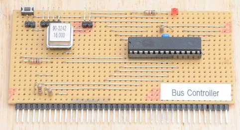
The behaviour of the bus controller has already been described. A slightly abbreviated version of the program it runs is shown below.
const byte microseconds = 1;
const byte pulse_width = 12 * microseconds;
const byte pulse_delay = 8 * microseconds;
const byte send_pins[] = {2, 3, ..., A0 };
const byte send_bits[] = {0b00000100, 0b00001000, ..., 0b00000001};
byte* const ports[] = {&PORTD, &PORTD, ..., &PORTC };
void setup()
{
for (byte i = 0; i < sizeof(send_pins); i = i + 1) pinMode(send_pins[i], OUTPUT);
for (byte i = 0; i < sizeof(send_pins); i = i + 1) digitalWrite(send_pins[i], HIGH);
}
void loop()
{
while (true)
{
PORTD = PORTD & ~send_bits[0];
delayMicroseconds(pulse_width);
PORTD = PORTD | send_bits[0];
delayMicroseconds(pulse_delay);
PORTD = PORTD & ~send_bits[1];
delayMicroseconds(pulse_width);
PORTD = PORTD | send_bits[1];
delayMicroseconds(pulse_delay);
...
PORTC = PORTC & ~send_bits[15];
delayMicroseconds(pulse_width);
PORTC = PORTC | send_bits[15];
delayMicroseconds(pulse_delay);
}
}
The ports array containing port register addresses is not actually used, but is helpful documentation for writing the main loop. Each of the pins defined in the send_pins array is aligned with the bit patten needed to access it and the port register which controls it. For each of the 16 send pins on the bus the same operations are performed in turn, output a 0 on the pin, delay by the required width of the negative going pulse, reset the pin to a 1, and then delay again to define the inter-pulse gap.
For short delays the delayMicroseconds function is not very precise, so the pulse_width and the pulse_delay constants were tuned using a logic analyser to observe the actual bus waveforms produced for the receive and received lines by the send and receive interrupt routines. The pulse width needs to be long enough for the sender to place data on the bus and assert the receive line, and for the receiver to read the data and assert the received line. The pulse delay needs to be just long enough for the sender and receiver to release their bus lines at the end of a communication before the send pulse for the next node occurs. With the values shown here the total time to perform a single communication is just under 20 microseconds.
A for-loop was not used in the main loop to iterate through the send_pins and other arrays, as the extra instructions required to manage a loop variable would have made tuning the output waveforms more difficult. It might be possible to rely on the GCC compiler's loop unrolling optimisations to generate the same code as that produced for the above program, but this has not been tried. This might also be combined with the use of an inline function to generate a single pulse on a single send line given appropriate parameters.
Next: Node Identifiers