Index

Firmware
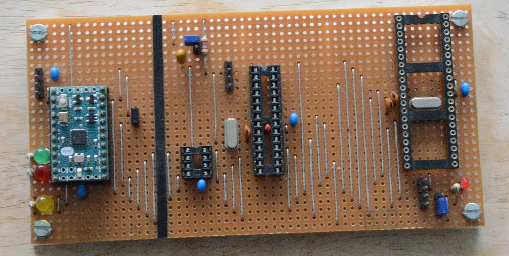
Bootloader firmware must be burn into blank 328 chips before programs can be uploaded into them using the Arduino IDE or similar software. This was done using the jig shown below and the Arduino as ISP software which is part of the Arduino IDE. The jig shown here allows bootloaders to be burn into 8, 28 and 40 pin chips under the control of the on-board Arduino Mini. However, it is not necessary to use a jig like this, as the necessary connections can be made to a blank 328 chip using prototyping board and an existing Arduino, e.g. an Arduino UNO.
The bootloader used for this system was the default Arduino Duemilanove bootloader, but the default bootloader for the Arduino Uno would do just as well. It is possible when burning a bootloader to specify things like the required clock frequency and how the clock should be provided, e.g. using an internal oscillator, an external oscillator or by using an external crystal. This is done by setting various internal fuses. The default bootloader used here is set up to use an external 16 MHz crystal. This was done to avoid the need to change any of the default settings even though an external clock source was to be used. The reason that this works is explained below.
A common way of building a crystal oscillator is illustrated by the following circuit.
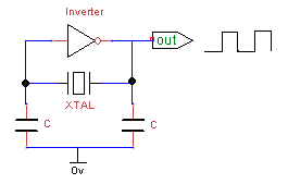
This uses a crystal, a pair of capacitors and an inverter, i.e. a NOT gate. With a suitable choice of capacitor values the output from this circuit will be a square wave with the frequency defined by the crystal. When using a 16 MHz external crystal with a 328 chip, it would usually be connected across the X1 and X2 pins with 22 picofarad capacitors connecting X1 and X2 to zero volts. In this case there is an inverting gate inside the 328 chip with its input connected to X1 and its output connected to X2. The actual clock oscillator is therefore identical to that shown in the above circuit with its output feeding the internal circuitry of the 328 via pin X2.
In the multi-processor system the chips are configured to use an external crystal, but the external crystal and capacitors are omitted, Instead, a common external clock is connected to all the X1 pins of all the 328 chips in the system, including the bus controller. In this case the internal inverter acts as an inverting buffer and feeds the clock signal directly to the X2 pin and hence to the rest of the processor.
The circuits presented here would work just as well with the fuses specifically set for an external clock. It would also be possible to use other external clock frequencies up to 20 MHz, but the internal fuses would need to be set to match or various components contained within the 328 chips, e.g. the serial USARTs, would not work correctly.