Index

Library Software
Click to download the library.
The ATmega 328 does not have any built-in ability to drive an 8-bit bus, let alone a 14-bit bus, which the multi-processor requires when node and port addressing is taken into account. The software must impose this structure on the hardware and in particular manage some fairly rapid events during the limited time periods scheduled by the bus controller for communication. Fortunately the GCC compiler generally used with the Arduino environment has a well developed optimiser and the software can easily be written in well structured C++ and there is no need to resort to low-level assembly language.
Some of the standard Arduino library functions, e.g. pinMode, digitalWrite and digitalRead, cannot be used here to implement the required bus operations. These were, quite rightly, designed for generality and ease of use rather than speed, which the majority of Arduino programs don't require. Instead, to get the bus operations done within the time available here it is necessary to deal with the 328 chip's port registers directly. This is not particularly complicated if manage systematically, but there is a lot more scope for errors, some of which can be very hard to find, than if the same operations could be written at a higher level using functions like digitalWrite.
Details of the use of port registers are provided here.
As many processing nodes have to be able to access the bus, no one processor can drive it all the time. When a processor is not driving the bus it must keep all the pins connected to it in a high impedance state, i.e. an input state. When the bus controller indicates, by using its send line, that a processor may attempt to send, some pins may then be set as outputs and their values defined appropriately. When the operation is complete, the bus must be released back to a high impedance state.
It is important that 2 of the bus lines receive and received remain at a high state when they are not being driven by any processor node. This is achieved by 2 1k pull-up resistors on the bus controller board. The non-driven states of the other lines are non-critical.
Communication Functions
A set of global variables is used to keep track of the communication status of a processing node. These are used by the sent_to and receive_on functions.
volatile byte node_id; // The processing nodes identifier set when the library is initialised
volatile bool sending; // Is the node currently sending
volatile bool receiving; // Is the node currently receiving
volatile bool received; // Has data been received
volatile byte data; // The data to be sent or that has been received
volatile byte sink_and_port; // A combination of the sink and port to be sent to
volatile byte receiver; // The sink and port information found on the bus during a receive operation
A set of constants define the port register bits used by the communication functions. Notice how the 8 data bits are split over ports B and D.
const byte send_pin = 2;
const byte receive_pin = 3;
const byte received_pin = 4;
//Port B
const int data_lo_bits = 0b00011111;
//Port C
const byte sink_bits = 0b00001111;
const byte port_bits = 0b00110000;
//Port D
const byte send_bit = 0b00000100;
const byte receive_bit = 0b00001000;
const byte received_bit = 0b00010000;
const byte data_hi_bits = 0b11100000;
A processing node will call the send_to function when it wishes to send data to another processing node. There are several variants of this function for different data types and with different ways of specifying the destination, but they all rely on the function shown below, which is used to send byte data to a specified node and port.
void send_to(byte value, byte sink, byte port)
{
data = value;
sink_and_port = sink & sink_bits | (port << 4) & port_bits;
sending = true;
attachInterrupt(digitalPinToInterrupt(send_pin), send_pin_change, CHANGE);
while (sending);
detachInterrupt(digitalPinToInterrupt(send_pin));
}
{
data = value;
sink_and_port = sink & sink_bits | (port << 4) & port_bits;
sending = true;
attachInterrupt(digitalPinToInterrupt(send_pin), send_pin_change, CHANGE);
while (sending);
detachInterrupt(digitalPinToInterrupt(send_pin));
}
The function stores the byte value to be sent in the global data variable and forms a single 6-bit value from the specified sink and port and stores it in the global sink_and_port variable. It then sets the sending variable to true to indicate that the nodes is attempting to send. An interrupt is then enabled so that a send_pin_change function will be called whenever a change occurs to the state of the send_pin (D2). This is connected to the bus line used by the bus controller to indicate to each node when it can take control of the bus. When the interrupt is enabled the function waits for the sending variable to be set to false by the interrupt routine. This will only happen when the data is sent successfully, i.e. the nominated node receives it on the indicated port.
When data is sent successfully, the function disables the interrupt and exits to allow the processing node to continue the execution of its task. Disabling the interrupt in this way ensures that processing nodes are not interrupted by the bus controller when they are not ready to send.
As with the send_to function there are a number of variants of the receive_on function for different data types, but they all rely on the function which is used to receive byte data from a specified port.
byte receive_on(byte port)
{
sink_and_port = node_id & sink_bits | (port << 4) & port_bits;
receiver = 0;
receiving = true;
received = false;
attachInterrupt(digitalPinToInterrupt(receive_pin), receive_pin_change, CHANGE);
while (receiving);
detachInterrupt(digitalPinToInterrupt(receive_pin));
return data;
}
{
sink_and_port = node_id & sink_bits | (port << 4) & port_bits;
receiver = 0;
receiving = true;
received = false;
attachInterrupt(digitalPinToInterrupt(receive_pin), receive_pin_change, CHANGE);
while (receiving);
detachInterrupt(digitalPinToInterrupt(receive_pin));
return data;
}
This function forms a 6-bit value from the node identifier of the node it is executed by and the value of the port argument and stores it in the sink_and_port variable. It then sets the receiver variable to 0. This variable will be loaded with the sink and port bits from the bus during an attempt to receive and compared with the sink_and_port variable to find out if data is being sent to the current receiver on the correct port. Pin change interrupts are then enabled so that a receive_pin_change function is called when the receive_pin (D3) changes state. After this, the function waits for the receiving variable to be set to false to indicate that data has been received by the interrupt routine. As with the send_to function, interrupts are disabled as soon as data has been received successfully.
The Send Interrupt Routine
When a node is sending, it will respond to changes of the state of the send pin (D2) by calling the send_pin_change interrupt routine.
void send_pin_change()
{
if ((PIND & send_bit) == 0) set_bus();
else
{
if ((PIND & received_bit) == 0) sending = false;
release_bus();
}
}
{
if ((PIND & send_bit) == 0) set_bus();
else
{
if ((PIND & received_bit) == 0) sending = false;
release_bus();
}
}
Either the pin will change from a 1 to a 0 when the bus controller is indicating that the node may send, or it will change from a 0 to a 1 to indicate the end of the send period. The function must read the state of the pin to decide if it is to initiate communication, or release the bus at the end of its allocated time. In the first case it calls the set_bus function to put data and destination information on to the bus and to set the appropriate control lines. In the second case, it tests to see if the receiver has set the received line and, if it has, sets the sending variable to false so that the send_to function can stop waiting and disable the interrupt (Note: the send_to function will not resume until the interrupt routine exits). After this, it releases the bus by calling the release_bus function.
The set_bus and release_bus functions are shown below. Note that both of these are declared inline to avoid the overhead of a normal function call.
inline void set_bus()
{
PORTC = sink_and_port;
PORTB = PORTB & ~data_lo_bits;
PORTB = PORTB | (data & data_lo_bits);
PORTD = PORTD & ~data_hi_bits;
PORTD = PORTD | (data & data_hi_bits);
PORTD = PORTD & ~receive_bit;
DDRB = DDRB | data_lo_bits;
DDRC = DDRC | sink_bits | port_bits;
DDRD = DDRD | data_hi_bits;
DDRD = DDRD | receive_bit;
}
Before the set_bus function starts all of the pins connected to the bus will be inputs. The function can therefore set the values it needs to place of the bus into the appropriate bits of the port output registers and then set the direction registers to cause the pins to output those values. The very last statement sets the pin corresponding to the receive line on the bus after the data and destination bits have been set. The bus lines to be read by the receiver will therefore be stable before the receive line is asserted.
inline void release_bus()
{
DDRC = DDRC & ~(sink_bits | port_bits);
DDRB = DDRB & ~data_lo_bits;
DDRD = DDRD & ~(data_hi_bits | receive_bit);
PORTC = PORTC | (sink_bits | port_bits);
PORTB = PORTB | data_lo_bits;
PORTD = PORTD | (data_hi_bits | receive_bit);
}
{
DDRC = DDRC & ~(sink_bits | port_bits);
DDRB = DDRB & ~data_lo_bits;
DDRD = DDRD & ~(data_hi_bits | receive_bit);
PORTC = PORTC | (sink_bits | port_bits);
PORTB = PORTB | data_lo_bits;
PORTD = PORTD | (data_hi_bits | receive_bit);
}
The of the release_bus function is simply to return all the lines driven by set_bus to inputs and to set the port output register to a default state.
The receive_bit_change function also has to determine the state of the pin it is monitoring by reading the pin (D3). On the falling edge it will read the sink and port bits and compare them with the sink_and_port variable. If they match, then the sender is sending to the current node on the port specified to the receive_on function. In this case the data lines are read from the bus into the data variable, the received line is asserted and the received variable is set to true.
On the rising edge of the receive line, the function places the received line back into an input state, in case it had been made an output, and sets the receiving variable to false only if data had in fact been received. This will allow the receive_on function to continue and disable the interrupt.
void receive_pin_change()
{
if ((PIND & receive_bit) == 0)
{
DDRC = DDRC & ~(sink_bits | port_bits);
receiver = PINC;
if (receiver == sink_and_port)
{
data = (PINB & data_lo_bits) | (PIND & data_hi_bits);
DDRD = DDRD | received_bit;
PORTD = PORTD & ~received_bit;
received = true;
}
}
else
{
DDRD = DDRD & ~received_bit;
PORTD = PORTD | received_bit;
if (received) receiving = false;
}
}
{
if ((PIND & receive_bit) == 0)
{
DDRC = DDRC & ~(sink_bits | port_bits);
receiver = PINC;
if (receiver == sink_and_port)
{
data = (PINB & data_lo_bits) | (PIND & data_hi_bits);
DDRD = DDRD | received_bit;
PORTD = PORTD & ~received_bit;
received = true;
}
}
else
{
DDRD = DDRD & ~received_bit;
PORTD = PORTD | received_bit;
if (received) receiving = false;
}
}
The interaction between a sending node and a receiving node can be seen in the following logic analyser trace.
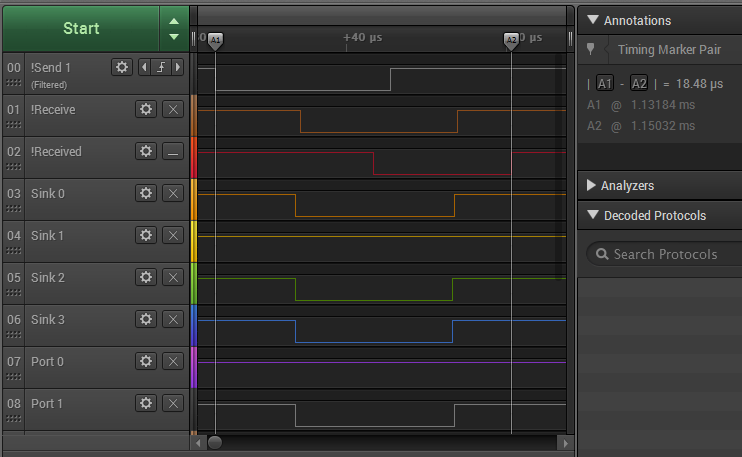
The top trace shows the bus controller's send signal to node 1. The orange trace shows the receive line dropping after the sink and port lines have been set to indicate port 1 on node 2.
The lag between the falling edge of the send line and the falling edge of the receive line is a result of the time taken by the set_pin_change to put its data on to the bus. There is a similar lag between the falling edge of the receive line, which triggers the receive_pin_change in node 2, and the falling edge of the received line. Finally, in response to the rising edge of the send line, node 1 releases the receive line, which has a 1k pull-up resistor connected to it, and in response to this the node 2 release the received line, which is also connected to a 1k pull-up resistor.
The time interval between the two white time markers, A1 and A2, is just under 18.5 microseconds.
Next: The Bus Controller