
Compact, Low Cost, DIY, Arduino Compatible
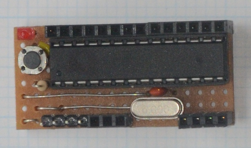
This article describes the construction of a compact, Arduino compatible board which can be used stand-alone, plugged into a prototyping board or built on to a larger board as part of a more complex project. It is 20mm by 44mm and uses an ATmega328 chip and can be programmed via a low cost USB to TTL serial cable using the Arduino IDE. The board is designed to be powered directly from the programming cable, therefore no on-board voltage regulator is required. Many low cost USB to TTL serial cables only provide four connections, i.e. 0v, 5v and TTL level Rx and Tx, with no reset line. Programming the chip therefore requires the reset button to be pressed as soon as the Arduino IDE status indicator changes from “Compiling sketch...” to “Uploading...”. Making the board using copper stripboard is straightforward and no custom PCB is required. Many people built “one-off” projects where the design and construction of a PCB is an unnecessary overhead, and the design described here can be fitted into one corner of a larger stripboard which may host other components and custom electronics.
Parts List
1 x 2,54mm (0.1") stripboard with at least 17 holes horizontally and 8 holes vertically with the copper strips running parallel to the short edge of the board.
1 x 28-pin DIL socket
1 x any ATmega328 chip, typically ATmega328P or ATmega328PU. It is best if this has already been flashed with a suitable boot-loader, i.e. Uno or Duemilanove.
1 x 16MHz crystal with approx 5.08mm (0.2") lead spacing.
2 x 22pf capacitors. These need to be relatively small disc type capacitors to fit the limited space available. See images in the Construction section.
1 x 1k resistor 0.25W.
1 x 470 ohm resistor 0.25W.
1 x Small LED to fit 2.54mm (0.1") hole spacing.
1 x Tactile switch for reset switch. Note: The one shown in the above image has two leads that will fit a 5.08mm hole spacing. Some similar switches with four leads may be difficult to fit in the available space.
1 x 4-way PCB socket strip.
Some short lengths of tinned copper wire.
In addition, either
1 x 3-way PCB header socket
1 x 4-way PCB header socket
1 x 14-way PCB header socket These can be made up from a number of smaller sockets but may need some filling to get them to fit side-by-side.
or
1 x 3-way PCB header plug
1 x 4-way PCB header plug
1 x 14-way PCB header plug These can be double ended plugs designed to take connection on both sides of a board or can be made from single sided plugs by carefully sliding the plastic spacer to one end of the pins with a straight edge such as a steel rule.
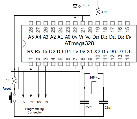
The Schematic
Very little circuitry is required to power and allow an ATmega328 chip to upload and run programs. The function of the majority of the pins on the chip will be determined by uploading software to it.
A typical USB to TTL Serial cable
Cables like this can be used to upload software to the board and communicate with programs when they are running. The black connection on the cable shown below is ground (0v), the red connection provides +5 volts (5v), the green connection provides transmitted data (Tx) from the computer the USB end of the cable is plugged into, and the white connection accepts data transmitted from, in this case, from the 328 chip. Other cables may vary. As long as you can determine which are the power connections on a specific cable, you should be able to work out the correct way round for the data connection by trial and error without damaging the chip. Always unplug the USB end of the cable before removing the connections to the board as transients can destroy the Rx input and prevent software from being uploaded.
Obviously it is important to get the 0v and 5v power connections the correct way round, but the serial connection will not function correctly if Rx and Tx are not connected the right way round. The Tx connection on the cable must be connected to Rx on the board, and Rx on the cable must be connected to Tx on the board. That is, when the computer transmits, the board must receive, and when the board transmits the computer must receive.
Connections like those shown in the picture below can be held together with a small piece of tape to keep them in the same order as the programming pins on the board, however you still have to remember to connect the whole thing the right way round!

Next: Construction