
Shields
• Development Kit
• Button and LED Shield
• Servo Shield
• Motor Shield
• Relay Shield
• Remote Shutter Release Shield
• ATtiny Programmer Shield
• Data Logging Shield
• DCC Decoder Shield
• Infrared Pulse Rate Monitor Shield
• I2C Bus Shield
Development Kit
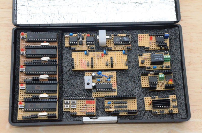
The picture shows a development kit containing five of the DIY micro-controller boards and a set of ten plug-in “shields”. This is useful for trying out ideas or temporarily interfacing to, or controlling, other hardware. Each shield plugs into the headers on a micro-controller board and is slightly shorter than the micro-controller board so that the LED and reset button are accessible. A cut-out in the lower left-hand corner allows access to the serial and power connector pins as shown below.
Button and LED Shield
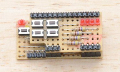
This picture shows a shield containing four buttons and four LEDs mounted on a micro-controller board. This is useful for testing out systems which need a number of digital inputs and which can display their state on a set of LEDs. The buttons allow D2, D3, D4 and D5 to be pulled down to zero volts. When in use, the associated input pins would usually have their internal pull-up resistors enabled.
Servo Shield
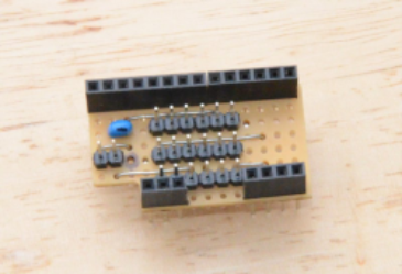
This shield provides connections for six servo motors using conventional three pin connectors. Power for the servos is provided via the two pins on the left-hand side.
Motor Shield
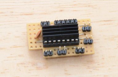
Using an L293D containing four half-bridges, this shield can be used to drive one stepper motor or two ordinary electric motors.
Relay Shield
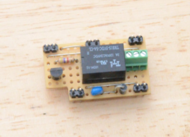
This relay shield uses a relay with change over contacts that can switch three amps at 120VAC or 24 volts DC.
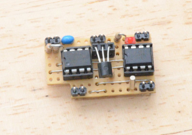
Remote Shutter Release Shield
A remote shutter release cable can be plugged into the 3.5mm jack socket on this shield to control both the shutter and auto-focus on a DSLR camera. It uses two opto isolator chips to isolate the camera from the micro-controller board.
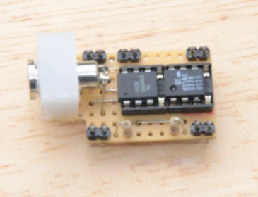
ATtiny Programmer Shield

Any of the 8-pin ATtiny 25/45/85 chips can be programmed by placing them in the socket on this shield and running “Arduino as ISP” on the micro-controller board using the Arduino IDE. The LED is connected to pin 3 and the link allows the reset pin to be disconnected from the main controller so that the ATtiny can run independently.
Data Logging Shield
This shield contains a 64k serial EPROM and a DS1320 real-time clock. The micro-controller can access both of these via I2C. There is also a socket for a DS18B20 temperature sensor, which the micro-controller can access using the “OneWire” library. The LED connected to the real-time clock can be programmed to flash every second.
DCC Decoder Shield

When connected to the track of a digital model railway via the green socket, this shield can feed an optically isolated version of the DCC signal to the micro-controller for decoding. The LED indicates when the track is “live” by rectifying power from the DCC signal.
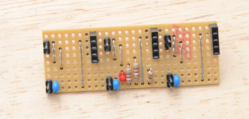
Infrared Pulse Rate Monitor Shield

This shield is slightly wider than the shields shown above, but plugs into the micro-controller boards in the same way. It uses a dual operational amplifier to filter and amplify the output of an infrared detector diode. The detector is mounted through a hole in the white nylon block shown on the left-hand side. An infrared LED is mounted alongside it in such a way that no light from the LED reaches the detector. If a finger is pressed over the LED and the detector, the amount of light refracted through the finger into the detector varies with blood pressure changes during the normal heartbeat cycle. The signal from the detector is connected to one of the analogue inputs of the micro-controller and can be analysed to determine a pulse rate / heartbeat rate.
I2C Bus Shield
This shield allows two or three micro-controller boards to be connected together by a common I2C bus. This is useful for testing systems which require master/slave communication with one or two slaves. The following picture shows three micro-controller boards plugged into the bus.
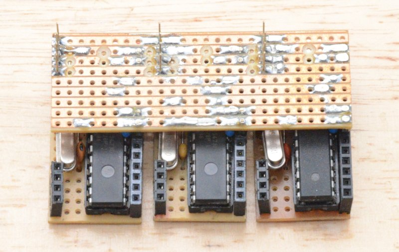
The pins sticking out of the top of the bus allow the three micro-controllers to be programmed independently, either by using separate serial adapters or by swapping a single serial adapter between the three sets of pins. Power from a serial adapter connected to any socket is distributed to all three micro-controllers.